
Electromagnetic radiation
The electromagnetic waves that compose electromagnetic radiation can be imagined as a self-propagating transverse oscillating wave of electric and magnetic fields. This diagram shows a plane linearly polarized EMR wave propagating from left to right. The electric field is in a vertical plane and the magnetic field in a horizontal plane. The two types of fields in EMR waves are always in phase with each other with a fixed ratio of electric to magnetic field intensity.
 Electromagnetic radiation (EM radiation or EMR) is one of the fundamental phenomena of electromagnetism, behaving as waves propagating through space, and also as photon particles traveling through space, carrying radiant energy. In a vacuum, it propagates at a characteristic speed, the speed of light, normally in straight lines. EMR is emitted and absorbed by charged particles. As an electromagnetic wave, it has both electric and magnetic field components, which oscillate in a fixed relationship to one another, perpendicular to each other and perpendicular to the direction of energy and wave propagation.
EMR is characterized by the frequency or wavelength of its wave. The electromagnetic spectrum, in order of increasing frequency and decreasing wavelength, consists of radio waves, microwaves, infrared radiation,visible light, ultraviolet radiation, X-rays and gamma rays. The eyes of various organisms sense a somewhat variable but relatively small range of frequencies of EMR called the visible spectrum orlight. Higher frequencies correspond to proportionately more energy carried by each photon; for instance, a single gamma ray photon carries far more energy than a single photon of visible light.
Electromagnetic radiation is associated with EM fields that are free to propagate themselves without the continuing influence of the moving charges that produced them, because they have achieved sufficient distance from those charges. Thus, EMR is sometimes referred to as the far field. In this language, the near field refers to EM fields near the charges and current that directly produced them, as for example with simple magnets and static electricity phenomena. In EMR, the magnetic and electric fields are each induced by changes in the other type of field, thus propagating itself as a wave. This close relationship assures that both types of fields in EMR stand in phase and in a fixed ratio of intensity to each other, with maxima and nodes in each found at the same places in space.
EMR carries energy—sometimes called radiant energy—through space continuously away from the source (this is not true of the near-field part of the EM field). EMR also carries both momentum and angular momentum. These properties may all be imparted to matter with which it interacts. EMR is produced from other types of energy when created, and it is converted to other types of energy when it is destroyed. The photon is the quantum of the electromagnetic interaction, and is the basic "unit" or constituent of all forms of EMR. The quantum nature of light becomes more apparent at high frequencies (thus high photon energy). Such photons behave more like particles than lower-frequency photons do.
In classical physics, EMR is considered to be produced when charged particles are accelerated by forces acting on them. Electrons are responsible for emission of most EMR because they have low mass, and therefore are easily accelerated by a variety of mechanisms. Rapidly moving electrons are most sharply accelerated when they encounter a region of force, so they are responsible for producing much of the highest frequency electromagnetic radiation observed in nature. Quantum processes can also produce EMR, such as when atomic nuclei undergo gamma decay, and processes such as neutral pion decay.
The effects of EMR upon biological systems (and also to many other chemical systems, under standard conditions) depends both upon the radiation's power and frequency. For lower frequencies of EMR up to those of visible light (i.e., radio, microwave, infrared), the damage done to cells and also to many ordinary materials under such conditions is determined mainly by heating effects, and thus by the radiation power. By contrast, for higher frequency radiations at ultraviolet frequencies and above (i.e., X-rays and gamma rays) the damage to chemical materials and living cells by EMR is far larger than that done by simple heating, due to the ability of single photons in such high frequency EMR to damage individual molecules chemically.
Maxwell’s equations for EM fields far from sources
James Clerk Maxwell first formally postulated electromagnetic waves. These were subsequently confirmed by Heinrich Hertz. Maxwell derived a wave form of the electric and magnetic equations, thus uncovering the wave-like nature of electric and magnetic fields, and their symmetry. Because the speed of EM waves predicted by the wave equation coincided with the measured speed of light, Maxwell concluded that light itself is an EM wave.
According to Maxwell's equations, a spatially varying electric field is always associated with a magnetic field that changes over time. Likewise, a spatially varying magnetic field is associated with specific changes over time in the electric field. In an electromagnetic wave, the changes in the electric field are always accompanied by a wave in the magnetic field in one direction, and vice versa.
This relationship between the two occurs without either type field causing the other; rather they occur together in the same way that time and space changes occur together and are interlinked in special relativity (In fact, magnetic fields may be viewed as relativistic distortions of electric fields, so the close relationship between space and time changes here is more than an analogy). Together, these fields form a propagating electromagnetic wave, which moves out into space and need never again affect the source. The distant EM field formed in this way by the acceleration of a charge carries energy with it that "radiates" away through space, hence the term for it.
This relationship between the two occurs without either type field causing the other; rather they occur together in the same way that time and space changes occur together and are interlinked in special relativity (In fact, magnetic fields may be viewed as relativistic distortions of electric fields, so the close relationship between space and time changes here is more than an analogy). Together, these fields form a propagating electromagnetic wave, which moves out into space and need never again affect the source. The distant EM field formed in this way by the acceleration of a charge carries energy with it that "radiates" away through space, hence the term for it.


The physics of electromagnetic radiation is electrodynamics. Electromagnetism is the physical phenomenon associated with the theory of electrodynamics. Electric and magnetic fields obey the properties of superposition. Thus, a field due to any particular particle or time-varying electric or magnetic field contributes to the fields present in the same space due to other causes.
Further, as they are vector fields, all magnetic and electric field vectors add together according to vector addition. For example, in optics two or more coherent lightwaves may interact and by constructive or destructive interference yield a resultant irradiance deviating from the sum of the component irradiances of the individual lightwaves.
Since light is an oscillation it is not affected by travelling through static electric or magnetic fields in a linear medium such as a vacuum. However in nonlinear media, such as some crystals, interactions can occur between light and static electric and magnetic fields — these interactions include the Faraday effect and the Kerr effect.
In refraction, a wave crossing from one medium to another of different density alters its speed and direction upon entering the new medium. The ratio of the refractive indices of the media determines the degree of refraction, and is summarized by Snell's law.
Light of composite wavelengths (natural sunlight) disperses into a visible spectrum passing through a prism, because of the wavelength dependent refractive index of the prism material (dispersion); that is, each component wave within the composite light is bent a different amount.[citation needed]
Light of composite wavelengths (natural sunlight) disperses into a visible spectrum passing through a prism, because of the wavelength dependent refractive index of the prism material (dispersion); that is, each component wave within the composite light is bent a different amount.[citation needed]
EM radiation exhibits both wave properties and particle properties at the same time. Both wave and particle characteristics have been confirmed in a large number of experiments. Wave characteristics are more apparent when EM radiation is measured over relatively large timescales and over large distances while particle characteristics are more evident when measuring small timescales and distances.
For example, when electromagnetic radiation is absorbed by matter, particle-like properties will be more obvious when the average number of photons in the cube of the relevant wavelength is much smaller than 1. It is not too difficult to experimentally observe non-uniform deposition of energy when light is absorbed, however this alone is not evidence of "particulate" behavior of light. Rather, it reflects the quantum nature of matter.Demonstrating that the light itself is quantized, not merely its interaction with matter, is a more subtle problem.
For example, when electromagnetic radiation is absorbed by matter, particle-like properties will be more obvious when the average number of photons in the cube of the relevant wavelength is much smaller than 1. It is not too difficult to experimentally observe non-uniform deposition of energy when light is absorbed, however this alone is not evidence of "particulate" behavior of light. Rather, it reflects the quantum nature of matter.Demonstrating that the light itself is quantized, not merely its interaction with matter, is a more subtle problem.
There are experiments in which the wave and particle natures of electromagnetic waves appear in the same experiment, such as the self-interference of a single photon. True single-photon experiments (in a quantum optical sense) can be done today in undergraduate-level labs. When a single photon is sent through an interferometer, it passes through both paths, interfering with itself, as waves do, yet is detected by a photomultiplier or other sensitive detector only once.
A quantum theory of the interaction between electromagnetic radiation and matter such as electrons is described by the theory ofquantum electrodynamics.
Electromagnetic spectrum
 |
Electromagnetic spectrum with visible light highlighted |
In general, EM radiation (the designation 'radiation' excludes static electric and magnetic and near fields) is classified by wavelength into radio, microwave, infrared, the visible spectrum we perceive as visible light, ultraviolet, X-rays, and gamma rays.
Arbitrary electromagnetic waves can always be expressed by Fourier analysis in terms of sinusoidal monochromatic waves, which in turn can each be classified into these regions of the EMR spectrum.
The behavior of EM radiation depends on its frequency. Lower frequencies have longer wavelengths, and higher frequencies have shorter wavelengths, and are associated with photons of higher energy.
There is no fundamental limit known to these wavelengths or energies, at either end of the spectrum, although photons with energies near the Planck energy or exceeding it (far too high to have ever been observed) will require new physical theories to describe.
Free-space path loss formula
Free-space path loss is proportional to the square of the distance between the transmitter and receiver, and also proportional to the square of the frequency of the radio signal.
Free-space path loss in decibels
A convenient way to express FSPL is in terms of dB:where the units are as before.
For in meters and kilohertz, respectively, the constant becomes
  . For in meters and megahertz, respectively, the constant becomes
  .
.
For in kilometers and megahertz, respectively, the constant becomes  .
.
FSPL (dB) = 32,45 + 20 log D + 20 log F
Physical explanation
where:
 is the power per unit area or power spatial density (in watts per metre-squared) at distance
  ,
,
 is the total power transmitted (in watts).
Note that this is not a frequency-dependent effect.
The second effect is that of the receiving antenna's aperture, which describes how well an antenna can pick up power from an incoming electromagnetic wave. For an isotropic antenna, this is given by
where is the received power. Note that this is entirely dependent on wavelength, which is how the frequency-dependent behaviour arises.
The total loss is given by the ratio
which can be found by combining the previous two expressions.
Parabolic antenna
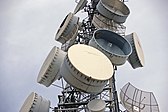
 Parabolic antennas have some of the highest gains, that is, they can produce the narrowest beam widths, of any antenna type. In order to achieve narrow beamwidths, the parabolic reflector must be much larger than the wavelength of the radio waves used, so parabolic antennas are used in the high frequency part of the radio spectrum, at UHF and microwave (SHF) frequencies, at which the wavelengths are small enough that conveniently-sized reflectors can be used.

Arbitrary electromagnetic waves can always be expressed by Fourier analysis in terms of sinusoidal monochromatic waves, which in turn can each be classified into these regions of the EMR spectrum.
The behavior of EM radiation depends on its frequency. Lower frequencies have longer wavelengths, and higher frequencies have shorter wavelengths, and are associated with photons of higher energy.
There is no fundamental limit known to these wavelengths or energies, at either end of the spectrum, although photons with energies near the Planck energy or exceeding it (far too high to have ever been observed) will require new physical theories to describe.
Soundwaves are not electromagnetic radiation. At the lower end of the electromagnetic spectrum, about 20 Hz to about 20 kHz, are frequencies that might be considered in the audio range.
However, electromagnetic waves cannot be directly perceived by human ears. Sound waves are the oscillating compression of molecules.
To be heard, electromagnetic radiation must be converted to pressure waves of the fluid in which the earis located (whether the fluid is air, water or something else).
Radio and microwave heating and currents, and infrared heating
When EM radiation interacts with matter, its behavior changes qualitatively as its frequency changes.
At radio and microwave frequencies, EMR interacts with matter largely as a bulk collection of charges which are spread out over large numbers of affected atoms.
In electrical conductors, such induced bulk movement of charges (electric currents) results in absorption of the EMR, or else separations of charges that cause generation of new EMR (effective reflection of the EMR).
An example is absorption or emission of radio waves by antennas, or absorption of microwaves by water or other molecules with an electric dipole moment, as for example inside a microwave oven. These interactions produce either electric currents or heat, or both. Infrared EMR interacts with dipoles present in single molecules, which change as atoms vibrate at the ends of a single chemical bond. For this reason, infrared is reflected by metals (as is most EMR into the ultraviolet) but is absorbed by a wide range of substances, causing them to increase in temperature as the vibrations dissipate as heat. In the same process, bulk substances radiate in the infrared spontaneously (see thermal radiation section below).
Reversible and nonreversible molecular changes from visible light
As frequency increases into the visible range, photons of EMR have enough energy to change the bond structure of some individual molecules. It is not a coincidence that this happens in the "visible range," as themechanism of vision involves the change in bonding of a single molecule (retinal) which absorbs light in the rhodopsin the retina of the human eye.
Photosynthesis becomes possible in this range as well, for similar reasons, as a single molecule of chlorophyll is excited by a single photon. Animals which detect infrared do not use such single molecule processes, but are forced to make use of small packets of water which change temperature, in an essentially thermal process that involves many photons (see infrared sensing in snakes). For this reason, infrared, microwaves, and radio waves are thought to damage molecules and biological tissue only by bulk heating, not excitation from single photons of the radiation (however, there does remain controversy about possible non-thermal biological damage from low frequency EM radiation, see below).
Visible light is able to affect a few molecules with single photons, but usually not in a permanent or damaging way, in the absence of power high enough to increase temperature to damaging levels. However, in plant tissues that carry on photosynthesis, carotenoids act to quench electronically excited chlorophyll produced by visible light in a process called non-photochemical quenching, in order to prevent reactions which would otherwise interfere with photosynthesis at high light levels. There is also some limited evidence that some reactive oxygen species are created by visible light in skin, and that these may have some role in photoaging, in the same manner as ultraviolet A does.
Free-space path loss
In telecommunication, free-space path loss (FSPL) is the loss in signal strength of an electromagnetic wave that would result from aline-of-sight path through free space (usually air), with no obstacles nearby to cause reflection or diffraction. It does not include factors such as the gain of the antennas used at the transmitter and receiver, nor any loss associated with hardware imperfections. A discussion of these losses may be found in the article on link budget.
Free-space path loss formula
Free-space path loss is proportional to the square of the distance between the transmitter and receiver, and also proportional to the square of the frequency of the radio signal.
The equation for FSPL is

where:
 is the signal wavelength (in metres),
 is the signal frequency (in hertz),
- is the distance from the transmitter (in metres),
 is the speed of light in a vacuum, 2.99792458 × 10⁸ metres per second.
This equation is only accurate in the far field where spherical spreading can be assumed; it does not hold close to the transmitter.
Free-space path loss in decibels
A convenient way to express FSPL is in terms of dB:where the units are as before.

For typical radio applications, it is common to find measured in units of GHz and in km, in which case the FSPL equation becomes
measured in units of GHz and in km, in which case the FSPL equation becomes
For
in meters and kilohertz, respectively, the constant becomes . For in meters and megahertz, respectively, the constant becomes .For
in kilometers and megahertz, respectively, the constant becomes .FSPL (dB) = 32,45 + 20 log D + 20 log F
Physical explanation
The FSPL expression above often leads to the erroneous belief that free space attenuates an electromagnetic wave according to its frequency. This is not the case, as there is no physical mechanism that could cause this.
The expression for FSPL actually encapsulates two effects. Firstly, the spreading out of electromagnetic energy in free space is determined by the inverse square law, i.e.

where:
is the power per unit area or power spatial density (in watts per metre-squared) at distance , is the total power transmitted (in watts).Note that this is not a frequency-dependent effect.

where
is the received power. Note that this is entirely dependent on wavelength, which is how the frequency-dependent behaviour arises.The total loss is given by the ratio

which can be found by combining the previous two expressions.
Parabolic antenna
A parabolic antenna is an antenna that uses a parabolic reflector, a curved surface with the cross-sectional shape of a parabola, to direct the radio waves. The most common form is shaped like a dish and is popularly called a dish antenna orparabolic dish. The main advantage of a parabolic antenna is that it has high directivity. It functions similarly to a searchlight or flashlight reflector to direct the radio waves in a narrow beam, or receive radio waves from one particular direction only.
 Parabolic antennas have some of the highest gains, that is, they can produce the narrowest beam widths, of any antenna type. In order to achieve narrow beamwidths, the parabolic reflector must be much larger than the wavelength of the radio waves used, so parabolic antennas are used in the high frequency part of the radio spectrum, at UHF and microwave (SHF) frequencies, at which the wavelengths are small enough that conveniently-sized reflectors can be used.
Parabolic antennas are used as high-gain antennas for point-to-point communications, in applications such as microwave relay links that carry telephone and television signals between nearby cities, wireless WAN/LAN links for data communications,satellite communications and spacecraft communication antennas.
They are also used in radio telescopes.
The other large use of parabolic antennas is for radar antennas, in which there is a need to transmit a narrow beam of radio waves to locate objects like ships, airplanes, and guided missiles.
With the advent of home satellite television receivers, parabolic antennas have become a common feature of the landscapes of modern countries.
Design
If a parabolic antenna is that a point source of radio waves at the focal point in front of a paraboloidal reflector of conductive material will be reflected into a collimated plane wave beam along the axis of the reflector. Conversely, an incoming plane wave parallel to the axis will be focused to a point at the focal point.

A typical parabolic antenna consists of a metal parabolic reflector with a small feed antenna suspended in front of the reflector at its focus, pointed back toward the reflector. The reflector is a metallic surface formed into a paraboloid of revolution and usually truncated in a circular rim that forms the diameter of the antenna.
In a transmitting antenna, radio frequency current from a transmitter is supplied through a transmission line cable to the feed antenna, which converts it into radio waves. The radio waves are emitted back toward the dish by the feed antenna and reflect off the dish into a parallel beam. In a receiving antenna the incoming radio waves bounce off the dish and are focused to a point at the feed antenna, which converts them to electric currents which travel through a transmission line to the radio receiver.
Parabolic reflector
 Wire grid-type parabolic antenna used for MMDS data link at a frequency of 2.5-2.7 GHz. It is fed by a vertical dipole under the small aluminum reflector on the boom. It radiates vertically polarized microwaves.
The reflector can be of sheet metal, metal screen, or wire grill construction, and it can be either a circular "dish" or various other shapes to create different beam shapes. A metal screen reflects radio waves as well as a solid metal surface as long as the holes are smaller than one-tenth of a wavelength, so screen reflectors are often used to reduce weight and wind loads on the dish.
To achieve the maximum gain, it is necessary that the shape of the dish be accurate within a small fraction of a wavelength, to ensure the waves from different parts of the antenna arrive at the focus in phase. Large dishes often require a supporting truss structure behind them to provide the required stiffness.
A reflector made of a grill of parallel wires or bars oriented in one direction acts as apolarizing filter as well as a reflector. It only reflects linearly polarized radio waves, with the electric field parallel to the grill elements. This type is often used in radar antennas. Combined with a linearly polarized feed horn, it helps filter out noise in the receiver and reduces false returns.
Feed antenna
The feed antenna at the reflector's focus is typically a low-gain type such as a half-wave dipole or more often a small horn antenna called a feed horn. In more complex designs, such as the Cassegrain and Gregorian, a secondary reflector is used to direct the energy into the parabolic reflector from a feed antenna located away from the primary focal point. The feed antenna is connected to the associated radio-frequency (RF) transmitting or receiving equipment by means of a coaxial cable transmission line or waveguide.

Waveguides
An advantage of parabolic antennas is that most of the structure of the antenna (all of it except the feed antenna) is non resonant, so it can function over a wide range of frequencies, that is a wide bandwidth. All that is necessary to change the frequency of operation is to replace the feed antenna with one that works at the new frequency. Some parabolic antennas transmit or receive at multiple frequencies by having several feed antennas mounted at the focal point, close together.
Dish parabolic antennas
 Shrouded microwave relay dishes on a communications tower in Australia.
 A satellite television dish, an example of an offset fed dish.
 Cassegrain satellite communication antenna in Sweden.
 Offset Gregorian antenna used in the Allen Telescope Array, aradio telescope at the University of California at Berkeley, USA.
Shaped-beam parabolic antennas
 Vertical "orange peel" antenna for military height finder radar, Germany.
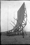 Early cylindrical parabolic antenna, 1931, Nauen, Germany.
 Air traffic control radar antenna, near Hannover, Germany.
 ASR-9 Airport surveillance radar antenna.
Gain
The directive qualities of an antenna are measured by a dimensionless parameter called its gain, which is the ratio of the power received by the antenna from a source along its beam axis to the power received by a hypothetical isotropic antenna.
The gain of a parabolic antenna is:

where: is the area of the antenna aperture, that is, the mouth of the parabolic reflector
 is the diameter of the parabolic reflector, if it is circular
 is the wavelength of the radio waves.
 is a dimensionless parameter between 0 and 1 called the aperture efficiency. The aperture efficiency of typical parabolic antennas is 0.55 to 0.70.
It can be seen that, as with any aperture antenna, the larger the aperture is, compared to the wavelength, the higher the gain. The gain increases with the square of the ratio of aperture width to wavelength, so large parabolic antennas, such as those used for spacecraft communication and radio telescopes, can have extremely high gain.
Applying the above formula to the 25-meter-diameter antennas often used in radio telescopearrays and satellite ground antennas at a wavelength of 21 cm (1.42 GHz, a common radio astronomy frequency), yields an approximate maximum gain of 140,000 times or about 50 dBi (decibels above the isotropic level).
Aperture efficiency eA is a catchall variable which accounts for various losses that reduce the gain of the antenna from the maximum that could be achieved with the given aperture. The major factors reducing the aperture efficiency in parabolic antennas are:.
Feed spillover - Some of the radiation from the feed antenna falls outside the edge of the dish and so doesn't contribute to the main beam.
Feed illumination taper - The maximum gain for any aperture antenna is only achieved when the intensity of the radiated beam is constant across the entire aperture area. However the radiation pattern from the feed antenna usually tapers off toward the outer part of the dish, so the outer parts of the dish are "illuminated" with a lower intensity of radiation. Even if the feed provided constant illumination across the angle subtended by the dish, the outer parts of the dish are farther away from the feed antenna than the inner parts, so the intensity would drop off with distance from the center. So the intensity of the beam radiated by a parabolic antenna is maximum at the center of the dish and falls off with distance from the axis, reducing the efficiency.
Aperture blockage - In front-fed parabolic dishes where the feed antenna is located in front of the dish in the beam path (and in Cassegrain and Gregorian designs as well), the feed structure and its supports block some of the beam. In small dishes such as home satellite dishes, where the size of the feed structure is comparable with the size of the dish, this can seriously reduce the antenna gain. To prevent this problem these types of antennas often use an offset feed, where the feed antenna is located to one side, outside the beam area. The aperture efficiency for these types of antennas can reach 0.7 to 0.8.
Shape errors - random surface errors in the shape of the reflector reduce efficiency. The loss is approximated by Ruze's Equation.
For theoretical considerations of mutual interference (at frequencies between 2 and c. 30 GHz - typically in the Fixed Satellite Service) where specific antenna performance has not been defined, a reference antenna based on Recommendation ITU-R S.465 is used to calculate the interference, which will include the likely sidelobes for off-axis effects.
he Cassegrain antenna design was adapted from the Cassegrain telescope, a type of reflecting telescope developed around 1672 and attributed to French priest Laurent Cassegrain. The first Cassegrain antenna was invented and built in Japan in 1963 by NTT, KDDI andMitsubishi Electric. The 20 meter I-1 antenna operated at 6.4, 4.2, and 1.7 GHz, and was used in October 1963 in the first trans-Pacific satellite television relay experiments.[6]

Parabolic reflector
Wire grid-type parabolic antenna used for MMDS data link at a frequency of 2.5-2.7 GHz. It is fed by a vertical dipole under the small aluminum reflector on the boom. It radiates vertically polarized microwaves.
The reflector can be of sheet metal, metal screen, or wire grill construction, and it can be either a circular "dish" or various other shapes to create different beam shapes. A metal screen reflects radio waves as well as a solid metal surface as long as the holes are smaller than one-tenth of a wavelength, so screen reflectors are often used to reduce weight and wind loads on the dish.
To achieve the maximum gain, it is necessary that the shape of the dish be accurate within a small fraction of a wavelength, to ensure the waves from different parts of the antenna arrive at the focus in phase. Large dishes often require a supporting truss structure behind them to provide the required stiffness.
A reflector made of a grill of parallel wires or bars oriented in one direction acts as apolarizing filter as well as a reflector. It only reflects linearly polarized radio waves, with the electric field parallel to the grill elements. This type is often used in radar antennas. Combined with a linearly polarized feed horn, it helps filter out noise in the receiver and reduces false returns.
Feed antenna
The feed antenna at the reflector's focus is typically a low-gain type such as a half-wave dipole or more often a small horn antenna called a feed horn. In more complex designs, such as the Cassegrain and Gregorian, a secondary reflector is used to direct the energy into the parabolic reflector from a feed antenna located away from the primary focal point. The feed antenna is connected to the associated radio-frequency (RF) transmitting or receiving equipment by means of a coaxial cable transmission line or waveguide.
 |
Waveguides |
An advantage of parabolic antennas is that most of the structure of the antenna (all of it except the feed antenna) is non resonant, so it can function over a wide range of frequencies, that is a wide bandwidth. All that is necessary to change the frequency of operation is to replace the feed antenna with one that works at the new frequency. Some parabolic antennas transmit or receive at multiple frequencies by having several feed antennas mounted at the focal point, close together.
Dish parabolic antennas

Shrouded microwave relay dishes on a communications tower in Australia.

A satellite television dish, an example of an offset fed dish.

Cassegrain satellite communication antenna in Sweden.

Offset Gregorian antenna used in the Allen Telescope Array, aradio telescope at the University of California at Berkeley, USA.
Shaped-beam parabolic antennas

Vertical "orange peel" antenna for military height finder radar, Germany.

Early cylindrical parabolic antenna, 1931, Nauen, Germany.

Air traffic control radar antenna, near Hannover, Germany.

ASR-9 Airport surveillance radar antenna.

where:
is the area of the antenna aperture, that is, the mouth of the parabolic reflector is the diameter of the parabolic reflector, if it is circular is the wavelength of the radio waves. is a dimensionless parameter between 0 and 1 called the aperture efficiency. The aperture efficiency of typical parabolic antennas is 0.55 to 0.70.It can be seen that, as with any aperture antenna, the larger the aperture is, compared to the wavelength, the higher the gain. The gain increases with the square of the ratio of aperture width to wavelength, so large parabolic antennas, such as those used for spacecraft communication and radio telescopes, can have extremely high gain.
Applying the above formula to the 25-meter-diameter antennas often used in radio telescopearrays and satellite ground antennas at a wavelength of 21 cm (1.42 GHz, a common radio astronomy frequency), yields an approximate maximum gain of 140,000 times or about 50 dBi (decibels above the isotropic level).
Aperture efficiency eA is a catchall variable which accounts for various losses that reduce the gain of the antenna from the maximum that could be achieved with the given aperture. The major factors reducing the aperture efficiency in parabolic antennas are:.
Feed spillover - Some of the radiation from the feed antenna falls outside the edge of the dish and so doesn't contribute to the main beam.
Feed illumination taper - The maximum gain for any aperture antenna is only achieved when the intensity of the radiated beam is constant across the entire aperture area. However the radiation pattern from the feed antenna usually tapers off toward the outer part of the dish, so the outer parts of the dish are "illuminated" with a lower intensity of radiation. Even if the feed provided constant illumination across the angle subtended by the dish, the outer parts of the dish are farther away from the feed antenna than the inner parts, so the intensity would drop off with distance from the center. So the intensity of the beam radiated by a parabolic antenna is maximum at the center of the dish and falls off with distance from the axis, reducing the efficiency.
Aperture blockage - In front-fed parabolic dishes where the feed antenna is located in front of the dish in the beam path (and in Cassegrain and Gregorian designs as well), the feed structure and its supports block some of the beam. In small dishes such as home satellite dishes, where the size of the feed structure is comparable with the size of the dish, this can seriously reduce the antenna gain. To prevent this problem these types of antennas often use an offset feed, where the feed antenna is located to one side, outside the beam area. The aperture efficiency for these types of antennas can reach 0.7 to 0.8.
Shape errors - random surface errors in the shape of the reflector reduce efficiency. The loss is approximated by Ruze's Equation.
For theoretical considerations of mutual interference (at frequencies between 2 and c. 30 GHz - typically in the Fixed Satellite Service) where specific antenna performance has not been defined, a reference antenna based on Recommendation ITU-R S.465 is used to calculate the interference, which will include the likely sidelobes for off-axis effects.
he Cassegrain antenna design was adapted from the Cassegrain telescope, a type of reflecting telescope developed around 1672 and attributed to French priest Laurent Cassegrain. The first Cassegrain antenna was invented and built in Japan in 1963 by NTT, KDDI andMitsubishi Electric. The 20 meter I-1 antenna operated at 6.4, 4.2, and 1.7 GHz, and was used in October 1963 in the first trans-Pacific satellite television relay experiments.[6]
Sem comentários:
Enviar um comentário