
Radar - (Radio Detection And Ranging)
Radar is an object detection system which uses radio waves to determine the range, altitude, direction, or speed of objects. It can be used to detect aircraft, ships, spacecraft, guided missiles,motor vehicles, weather formations, and terrain. The radar dish or antenna transmits pulses of radio waves or microwaves which bounce off any object in their path. The object returns a tiny part of the wave's energy to a dish or antenna which is usually located at the same site as the transmitter.
Radar was secretly developed by several nations before and during World War II. The term RADAR itself, not the actual development, was coined in 1940 by the United States Navy as an acronym for RAdio Detection And Ranging. The term radar has since entered English and other languages as the common noun radar, losing all capitalization.
The modern uses of radar are highly diverse, including air traffic control, radar astronomy, air-defense systems, antimissile systems; marine radars to locate landmarks and other ships; aircraft anticollision systems; ocean surveillance systems, outer space surveillance and rendezvous systems; meteorological precipitation monitoring; altimetry and flight control systems; guided missile target locating systems; and ground-penetrating radar for geological observations. High tech radar systems are associated with digital signal processing and are capable of extracting useful information from very high noise levels.
Other systems similar to radar make use of other parts of the electromagnetic spectrum. One example is "lidar", which uses visible light from lasers rather than radio waves.
RADAR History
As early as 1886, German physicist Heinrich Hertz showed that radio waves could be reflected from solid objects. In 1895, Alexander Popov, a physics instructor at the Imperial Russian Navy school in Kronstadt, developed an apparatus using a coherer tube for detecting distant lightning strikes. The next year, he added a spark-gap transmitter. In 1897, while testing this equipment for communicating between two ships in the Baltic Sea, he took note of an interference beat caused by the passage of a third vessel. In his report, Popov wrote that this phenomenon might be used for detecting objects, but he did nothing more with this observation.[2]
The German inventor Christian Hülsmeyer was the first to use radio waves to detect "the presence of distant metallic objects". In 1904 he demonstrated the feasibility of detecting a ship in dense fog, but not its distance from the transmitter. He obtained a patent for his detection device in April 1904 and later a patent for a related amendment for estimating the distance to the ship. He also got a British patent on September 23, 1904 for a full system, that he called a telemobiloscope.
 |
| A chain tower |
In 1922 A. Hoyt Taylor and Leo C. Young, researchers working with the U.S. Navy, had a transmitter and a receiver on opposite sides of the Potomac River and discovered that a ship passing through the beam path caused the received signal to fade in and out. Taylor submitted a report, suggesting that this might be used to detect the presence of ships in low visibility, but the Navy did not immediately continue the work.
Eight years later, Lawrence A. Hyland at the Naval Research Laboratory observed similar fading effects from a passing aircraft; this led to a patent applicationas well as a proposal for serious work at the NRL (Taylor and Young were then at this laboratory) on radio-echo signals from moving targets.
Eight years later, Lawrence A. Hyland at the Naval Research Laboratory observed similar fading effects from a passing aircraft; this led to a patent applicationas well as a proposal for serious work at the NRL (Taylor and Young were then at this laboratory) on radio-echo signals from moving targets.
Before the Second World War, researchers in France, Germany, Italy, Japan, the Netherlands, the Soviet Union, the United Kingdom, and the United States, independently and in great secrecy, developed technologies that led to the modern version of radar. Australia, Canada, New Zealand, and South Africa followed prewar Great Britain, and Hungary had similar developments during the war.
In France in 1934, following systematic studies on the magnetron, the research branch of the Compagnie Générale de Télégraphie Sans Fil (CSF), headed by Maurice Ponte, with Henri Gutton, Sylvain Berline, and M. Hugon began developing an obstacle-locating radio apparatus, a part of which was installed on the Normandie liner in 1935.
During the same time, the Soviet military engineer P. K. Oshchepkov, in collaboration with Leningrad Electrophysical Institute, produced an experimental apparatus, RAPID, capable of detecting an aircraft within 3 km of a receiver. The French and Soviet systems, however, had continuous-wave operation and could not give the full performance that was ultimately at the center of modern radar.
Full radar evolved as a pulsed system, and the first such elementary apparatus was demonstrated in December 1934 by the American Robert M. Page, working at the Naval Research Laboratory. The following year, the United States Army successfully tested a primitive surface-to-surface radar to aim coastal battery search lights at night. This was followed by a pulsed system demonstrated in May 1935 by Rudolf Kühnhold and the firm GEMA in Germany and then one in June 1935 by an Air Ministry team led by Robert A. Watson Watt in Great Britain.
Development of radar greatly expanded on 1 September 1936 when Watson-Watt became Superintendent of a new establishment under the British Air Ministry, Bawdsey Research Station located in Bawdsey Manor, near Felixstowe, Suffolk. Work there resulted in the design and installation of aircraft detection and tracking stations called Chain Home along the East and South coasts of England in time for the outbreak of World War II in 1939. This system provided the vital advance information that helped the Royal Air Force win the Battle of Britain.
The British were the first to fully exploit radar as a defence against aircraft attack. This was spurred on by fears that the Germans were developing death rays. The Air Ministry asked British scientists in 1934 to investigate the possibility of propagating electromagnetic energy and the likely effect. Following a study, they concluded that a death ray was impractical but that detection of aircraft appeared feasible. Robert Watson Watt's team demonstrated to his superiors the capabilities of a working prototype and then patented the device. It served as the basis for the Chain Home network of radars to defend Great Britain, which detected approaching German aircraft in the Battle of Britain in 1940.
In April 1940, Popular Science showed an example of a radar unit using the Watson-Watt patent in an article on air defence, but not knowing that the U.S. Army and U.S. Navy were working on radars with the same principle, stated under the illustration, "This is not U.S. Army equipment." Also, in late 1941 Popular Mechanics had an article in which a U.S. scientist speculated about the British early warning system on the English east coast and came close to what it was and how it worked. Alfred Lee Loomis organized the Radiation Laboratory at Cambridge, Massachusetts which developed the technology in the years 1941-45. Later, in 1943, Page greatly improved radar with the monopulse technique that was used for many years in most radar applications.
The war precipitated research to find better resolution, more portability, and more features for radar, including complementary navigation systems like Oboe used by the RAF's Pathfinder.
Applications
The information provided by radar includes the bearing and range (and therefore position) of the object from the radar scanner. It is thus used in many different fields where the need for such positioning is crucial. The first use of radar was for military purposes: to locate air, ground and sea targets. This evolved in the civilian field into applications for aircraft, ships, and roads.
 |
| Commercial marine radar antenna. |
In aviation, aircraft are equipped with radar devices that warn of aircraft or other obstacles in or approaching their path, display weather information, and give accurate altitude readings. The first commercial device fitted to aircraft was a 1938 Bell Lab unit on some United Air Lines aircraft. Such aircraft can land in fog at airports equipped with radar-assisted ground-controlled approach systems in which the plane's flight is observed on radar screens while operators radio landing directions to the pilot.
Marine radars are used to measure the bearing and distance of ships to prevent collision with other ships, to navigate, and to fix their position at sea when within range of shore or other fixed references such as islands, buoys, and lightships. In port or in harbour, vessel traffic service radar systems are used to monitor and regulate ship movements in busy waters.
Meteorologists use radar to monitor precipitation and wind. It has become the primary tool for short-term weather forecasting and watching for severe weather such as thunderstorms, tornadoes, winter storms, precipitation types, etc. Geologists use specialised ground-penetrating radars to map the composition of Earth's crust.
Police forces use radar guns to monitor vehicle speeds on the roads.
 Palmer Scan: A scanning technique that produces a scanning beam by moving the main antenna and its feed. A Palmer Scan is a combination of a Primary Scan and a Secondary Scan.
Reduction of interference effects
Signal processing is employed in radar systems to reduce the radar interference effects. Signal processing techniques include moving target indication, Pulse-Doppler signal processing, moving target detection processors, correlation with secondary surveillance radar targets, space-time adaptive processing, and track-before-detect. Constant false alarm rate and digital terrain model processing are also used in clutter environments.
Engineering

A radar's components are:
A transmitter that generates the radio signal with an oscillator such as a klystron or a magnetron and controls its duration by a modulator.
A waveguide that links the transmitter and the antenna.
A duplexer that serves as a switch between the antenna and the transmitter or the receiver for the signal when the antenna is used in both situations.
A receiver. Knowing the shape of the desired received signal (a pulse), an optimal receiver can be designed using a matched filter.
A display processor to produce signals for human readable output devices.
An electronic section that controls all those devices and the antenna to perform the radar scan ordered by software.
A link to end user devices and displays.
Antenna design
Radio signals broadcast from a single antenna will spread out in all directions, and likewise a single antenna will receive signals equally from all directions. This leaves the radar with the problem of deciding where the target object is located.
Early systems tended to use omnidirectional broadcast antennas, with directional receiver antennas which were pointed in various directions. For instance, the first system to be deployed, Chain Home, used two straight antennas at right angles for reception, each on a different display. The maximum return would be detected with an antenna at right angles to the target, and a minimum with the antenna pointed directly at it (end on).
The operator could determine the direction to a target by rotating the antenna so one display showed a maximum while the other showed a minimum. One serious limitation with this type of solution is that the broadcast is sent out in all directions, so the amount of energy in the direction being examined is a small part of that transmitted. To get a reasonable amount of power on the "target", the transmitting aerial should also be directional.
Parabolic reflector
More modern systems use a steerable parabolic "dish" to create a tight broadcast beam, typically using the same dish as the receiver. Such systems often combine two radar frequencies in the same antenna in order to allow automatic steering, or radar lock.
Parabolic reflectors can be either symmetric parabolas or spoiled parabolas: Symmetric parabolic antennas produce a narrow "pencil" beam in both the X and Y dimensions and consequently have a higher gain. The NEXRAD Pulse-Doppler weather radar uses a symmetric antenna to perform detailed volumetric scans of the atmosphere. Spoiled parabolic antennas produce a narrow beam in one dimension and a relatively wide beam in the other. This feature is useful if target detection over a wide range of angles is more important than target location in three dimensions.
Most 2D surveillance radars use a spoiled parabolic antenna with a narrow azimuthal beamwidth and wide vertical beamwidth. This beam configuration allows the radar operator to detect an aircraft at a specific azimuth but at an indeterminate height. Conversely, so-called "nodder" height finding radars use a dish with a narrow vertical beamwidth and wide azimuthal beamwidth to detect an aircraft at a specific height but with low azimuthal precision.
Types of scan
Primary Scan: A scanning technique where the main antenna aerial is moved to produce a scanning beam, examples include circular scan, sector scan, etc.
Secondary Scan: A scanning technique where the antenna feed is moved to produce a scanning beam, examples include conical scan, unidirectional sector scan, lobe switching, etc.
Palmer Scan: A scanning technique that produces a scanning beam by moving the main antenna and its feed. A Palmer Scan is a combination of a Primary Scan and a Secondary Scan.
Slotted waveguide antenna
Applied similarly to the parabolic reflector, the slotted waveguide is moved mechanically to scan and is particularly suitable for non-tracking surface scan systems, where the vertical pattern may remain constant.
Owing to its lower cost and less wind exposure, shipboard, airport surface, and harbour surveillance radars now use this approach in preference to a parabolic antenna.
Microwave Ovens
The microwave radiation of microwave ovens and some radar applications is produced by a device called a magnetron. Modern microwave overns operate at the frequency 2,450 MHz
 Considering the frequency of 2,450 MHz, the wavelength of microwave oven radiation is about 12 cm and the quantum energy of a microwave photon is about 1 x 10⁻⁵ eV. The radiation interaction at such energies is limited to the production of molecular rotation and torsion.
The microwave radiation of microwave ovens and some radar applications is produced by a device called a magnetron. Modern microwave overns operate at the frequency 2,450 MHz
By federal regulation, microwave ovens are limited to 5 milliwatts (mW) of microwave radiation per square centimeter at approximately 2 inches from the oven surface. This limit is far below the level known to harm people. The microwave radiation would be expected to drop off according to the inverse square law, so at 20 inches it would be down by about a factor of 100.
Considering the frequency of 2,450 MHz, the wavelength of microwave oven radiation is about 12 cm and the quantum energy of a microwave photon is about 1 x 10⁻⁵ eV. The radiation interaction at such energies is limited to the production of molecular rotation and torsion.
The average thermal energy at 20°C is about 1/40 eV, so any ordered rotational motion created by the microwave interaction is quickly randomized by collisions with molecules of kinetic energy 2500 times greater than the microwave photon energy provided. So the net result of microwave interaction in microwave ovens is to heat the material in the oven.
Even though you can see into the microwave oven when your food is cooking, the microwaves are effectively blocked from getting out into the room because the holes in the metal screen on the microwave oven door are about 1 mm in diameter compared to a 120 mm wavelength for the microwaves.
The wavelength of the microwaves is about 120 times the size of the holes, and can't "see" the holes to get out. This is an application of the fact that you cannot image anything that is smaller than the wavelength of the radiation you use to image it. You can see through the holes because at 500 nm wavelength, the light wavelength is about 2000 times smaller than the holes.
The Magnetron
The microwave radiation of microwave ovens and some radar applications is produced by a device called a magnetron.
The magnetron is called a "crossed-field" device in the industry because both magnetic and electric fields are employed in its operation, and they are produced in perpendicular directions so that they cross. The applied magnetic field is constant and applied along the axis of the circular device illustrated. The power to the device is applied to the center cathode which is heated to supply energetic electrons which would, in the absence of the magnetic field, tend to move radially outward to the ring anode which surrounds it.
Electrons are released at the center hot cathode by the process of thermionic emission and have an accelerating field which moves them outward toward the anode. The axial magnetic field exerts a magnetic force on these charges which is perpendicular to their initially radial motion, and they tend to be swept around the circle. In this way, work is done on the charges and therefore energy from the power supply is given to them.
As these electrons sweep toward a point where there is excess negative charge, that charge tends to be pushed back around the cavity, imparting energy to the oscillation at the natural frequency of the cavity. This driven oscillation of the charges around the cavities leads to radiation of electromagnetic waves, the output of the magnetron.
Electromagnetic Wave Equation
The wave equation for a plane electric wave traveling in the x direction in space is
with the same form applying to the magnetic field wave in a plane perpendicular the electric field. Both the electric field and the magnetic field are perpendicular to the direction of travel x. The symbol c represents the speed of light or other electromagnetic waves. The wave equation for electromagnetic waves arises from Maxwell's equations. The form of a plane wave solution for the electric field is
and that for the magnetic field
To be consistent with Maxwell's equations, these solutions must be related by

The magnetic field B is perpendicular to the electric field E in the orientation where the vector product E x B is in the direction of the propagation of the wave.
Electromagnetic waves carry energy as they travel through empty space. There is an energy density associated with both the electric and magnetic fields. The rate of energy transport per unit area is described by the vector
which is called the Poynting vector. This expression is a vector product, and since the magnetic field is perpendicular to the electric field, the magnitude can be written
The rate of energy transport S is perpendicular to both E and B and in the direction of propagation of the wave. A condition of the wave solution for a plane wave is Bm = Em/c so that the average intensity for a plane wave can be written
This makes use of the fact that the average of the square of a sinusoidal function over a whole number of periods is just 1/2.
Phased array
Another method of steering is used in a phased array radar.
Phase array antennas are composed of evenly spaced similar antenna elements, such as aerials or rows of slotted waveguide. Each antenna element or group of antenna elements incorporates a discreet phase shift that produces a phase gradient across the array.
For example, array elements producing a 5 degree phase shift for each wavelength across the array face will produce a beam pointed 5 degree away from the centerline perpendicular to the array face. Signals traveling along that beam will be reinforced. Signals offset from that beam will be canceled. The amount of reinforcement is antenna gain.
The amount of cancellation is side-lobe suppression.
Phased array radars have been in use since the earliest years of radar in World War II, but electronic device limitations led to poor performance. Phased array radars were originally used for missile defense. They are the heart of the ship-borne Aegis combat systemand the Patriot Missile System. The massive redundancy associated with having a large number of array elements increases reliability at the expense of gradual performance degradation that occurs as individual phase elements fail.
Phased array antenna can be built to conform to specific shapes, like missiles, infantry support vehicles, ships, and aircraft.
As the price of electronics has fallen, phased array radars have become more common. Almost all modern military radar systems are based on phased arrays, where the small additional cost is offset by the improved reliability of a system with no moving parts. Traditional moving-antenna designs are still widely used in roles where cost is a significant factor such as air traffic surveillance, weather radars and similar systems.
Phased array radars are valued for use in aircraft since they can track multiple targets. The first aircraft to use a phased array radar was the B-1B Lancer. The first aircraft fighter to use phased array radar was the Mikoyan MiG-31. The MiG-31M's SBI-16 Zaslon phased array radar is considered to be the world's most powerful fighter radar.
Phased-array interferometry or aperture synthesis techniques, using an array of separate dishes that are phased into a single effective aperture, are not typical for radar applications, although they are widely used in radio astronomy. Because of the thinned array curse, such multiple aperture arrays, when used in transmitters, result in narrow beams at the expense of reducing the total power transmitted to the target. In principle, such techniques could increase spatial resolution, but the lower power means that this is generally not effective.
Aperture synthesis by post-processing motion data from a single moving source, on the other hand, is widely used in space andairborne radar systems .
Phased array
This article is about general theory and electromagnetic phased array. For the ultrasonic and medical imaging application, seephased array ultrasonics. For the optical application, see phased-array optics.
PAVE PAWS phased array radar in Alaska
|
in antenna theory, a phased array is an array of antennas in which the relative phases of the respective signals feeding the antennas are varied in such a way that the effective radiation pattern of the array is reinforced in a desired direction and suppressed in undesired directions.

 |
| Mammut phased array radar World War II |
An antenna array is a group of multiple active antennas coupled to a common source or load to produce a directive radiation pattern. Usually, the spatial relationship of the individual antennas also contributes to the directivity of the antenna array.
Use of the term "active antennas" is intended to describe elements whose energy output is modified due to the presence of a source of energy in the element (other than the mere signal energy which passes through the circuit) or an element in which the energy output from a source of energy is controlled by the signal input. One common application of this is with a standard multiband television antenna, which has multiple elements coupled together.
History- Three Nobel Prizes
Phased array transmission was originally developed in 1905 by Nobel Laureate Karl Ferdinand Braun who demonstrated enhanced transmission of radio waves in one direction. During World War II, Nobel Laureate Luis Alvarez used phased array transmission in a rapidly-steerable radar system for "ground-controlled approach", a system to aid in the landing of aircraft.
At the same time, the GEMA in Germany built the PESA Mammut 1. It was later adapted for radio astronomy leading to Nobel Prizes for Physics for Antony Hewish and Martin Ryle after several large phased arrays were developed at the University of Cambridge.
The design is also used in radar, and is generalized in interferometric radio antennas. In 2007, DARPA researchers announced a 16 element phased array integrated with all necessary circuits to send at 30–50 GHz on a single silicon chip for military purposes.
Broadcasting
Naval usage
Broadcasting
In broadcast engineering, it is required that phased arrays be used by many AM broadcast radio stations to enhance signal strength and therefore coverage in the city of license, while minimizing interference to other areas. Due to the differences between daytime and nighttime ionospheric propagation at mediumwave frequencies, it is common for AM broadcast stations to change between day (groundwave) and night (skywave) radiation patterns by switching the phase and power levels supplied to the individual antenna elements (mast radiators) daily at sunrise and sunset. More modest phased array longwire antenna systems may be employed by private radio enthusiasts to receive longwave, mediumwave (AM) and shortwave radio broadcasts from great distances.
On VHF, phased arrays are used extensively for FM broadcasting. These greatly increase the antenna gain, magnifying the emitted RF energy toward the horizon, which in turn greatly increases a station's broadcast range. In these situations, the distance to each element from the transmitter is identical, or is one (or other integer) wavelength apart. Phasing the array such that the lower elements are slightly delayed (by making the distance to them longer) causes a downward beam tilt, which is very useful if the antenna is quite high on a radio tower.
 |
Kathrein's professional antenna |
Other phasing adjustments can increase the downward radiation in the far field without tilting the main lobe, creating null fill to compensate for extremely high mountaintop locations, or decrease it in the near field, to prevent excessive exposure to those workers or even nearby homeowners on the ground. The latter effect is also achieved by half-wave spacing – inserting additional elements halfway between existing elements with full-wave spacing. This phasing achieves roughly the same horizontal gain as the full-wave spacing; that is, a five-element full-wave-spaced array equals a nine- or ten-element half-wave-spaced array.
Naval usage
Phased array radar systems are also used by warships of many navies. Because of the rapidity with which the beam can be steered, phased array radars allow a warship to use one radar system for surface detection and tracking (finding ships), air detection and tracking (finding aircraft and missiles) and missile uplink capabilities.
Before using these systems, each surface-to-air missile in flight required a dedicated fire-control radar, which meant that ships could only engage a small number of simultaneous targets. Phased array systems can be used to control missiles during the mid-course phase of the missile's flight. During the terminal portion of the flight, continuous-wave fire control directors provide the final guidance to the target.

Because the radar beam is electronically steered, phased array systems can direct radar beams fast enough to maintain a fire control quality track on many targets simultaneously while also controlling several in-flight missiles. The AN/SPY-1 phased array radar, part of the Aegis combat system deployed on modern U.S.cruisers and destroyers, "is able to perform search, track and missile guidance functions simultaneously with a capability of over 100 targets."
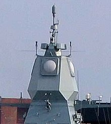
Likewise, the Thales Herakles phased array multi-function radar on board the Formidable class frigates of the Republic of Singapore Navy has a track capacity of 200 targets and is able to achieve automatic target detection, confirmation and track initiation in a single scan, while simultaneously providing mid-course guidance updates to the MBDA Aster missiles launched from the ship.[8]The German Navy and the Dutch Navy have developed the Active Phased Array Radar System (APAR).
Active Phased Array Radar mounted on top of Sachsen class frigate F220Hamburg's superstructure of the German Navy.See also: Active Electronically Scanned Array, Aegis combat system and AN/SPY-1
Phased arrays are used in naval sonar, in active (transmit and receive) and passive (receive only) and hull-mounted and towed array sonar.
Weather research usage

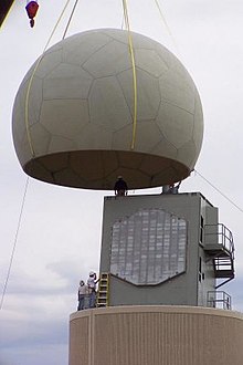
AN/SPY-1A radar installation at NSSL, Norman, Oklahoma. The round dome primarily provides weather protection.
The National Severe Storms Laboratory has been using a SPY-1A phased array antenna, provided by the US Navy, for weather research at its Norman, Oklahoma facility since April 23, 2003. It is hoped that research will lead to a better understanding of thunderstorms and tornadoes, eventually leading to increased warning times and enhanced prediction of tornadoes.
Current project participants include the National Severe Storms Laboratory and National Weather Service Radar Operations Center, Lockheed Martin, United States Navy, University of Oklahoma School of Meteorology, School of Electrical and Computer Engineering, and Atmospheric Radar Research Center, Oklahoma State Regents for Higher Education, the Federal Aviation Administration, and Basic Commerce and Industries.
The project includes research and development, future technology transfer and potential deployment of the system throughout the United States. It is expected to take 10 to 15 years to complete and initial construction was approximately $25 million.
Optics
Within the visible or infrared spectrum of electromagnetic waves it is possible to construct optical phased arrays. They are used in wavelength multiplexers and filters for telecommunication purposes, laser beam steering, and holography. Synthetic array heterodyne detection is an efficient method for multiplexing an entire phased array onto a single element photodetector.
Mathematical perspective and formulas
A phased array is an example of N-slit diffraction. It may also be viewed as the coherent addition of N line sources. Since each individual antenna acts as a slit, emitting radio waves, their diffraction pattern can be calculated by adding the phase shift φ to the fringing term.
We will begin from the N-slit diffraction pattern derived on the diffraction formalism page.

Now, adding a φ term to the  fringe effect in the second term yields:
fringe effect in the second term yields:
Taking the square of the wave function gives us the intensity of the wave.


Now space the emitters a distance  apart. This distance is chosen for simplicity of calculation but can be adjusted as any scalar fraction of the wavelength.
apart. This distance is chosen for simplicity of calculation but can be adjusted as any scalar fraction of the wavelength.
As sine achieves its maximum at  , we set the numerator of the second term = 1.
, we set the numerator of the second term = 1.

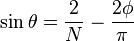
Thus as N gets large, the term will be dominated by the  term. As sine can oscillate between −1 and 1, we can see that setting
  will send the maximum energy on an angle given by
term. As sine can oscillate between −1 and 1, we can see that setting will send the maximum energy on an angle given by
Additionally, we can see that if we wish to adjust the angle at which the maximum energy is emitted, we need only to adjust the phase shift φ between successive antennas. Indeed the phase shift corresponds to the negative angle of maximum signal.
A similar calculation will show that the denominator is minimized by the same factor.
Dynamic Phased Array
Each array element incorporates an adjustable phase shifter that are collectively used to move the beam with respect to the array face.
Dynamic phase array require no physical movement to aim the beam. The beam is moved electronically. This can produce antenna motion fast enough to use a small pencil-beam to simultaneously track multiple targets while searching for new targets using just one radar set (track while search).
As an example, an antenna with a 2 degree beam with a pulse rate of 1 kHz will require approximately 16 seconds to cover an entire a hemisphere consisting of 16,000 pointing positions. This configuration provides 6 opportunities to detect a Mach 3 vehicle over a range of 100 km (62 mi), which is suitable for military applications.
The position of mechanically steered antennas can be predicted, which can be used to create electronic countermeasures that interfere with radar operation. The flexibility resulting from phase array operation allows beams to be aimed at random locations, which eliminates this vulnerability. This is also desirable for military applications.
Fixed Phase Array
Fixed phase array antennas are typically used to create an antenna with a more desirable form factor than the conventional parabolic reflector or cassegrain reflector. Fixed phased array radar incorporate fixed phase shifters. This kind of phase array is physically moved during the track and scan process. There are two configurations:
A) - Multiple frequencies with a delay-line
B) - Multiple adjacent beams
The SPS-48 radar uses multiple transmit frequencies with a serpentine delay line along the left side of the array to produce vertical fan of stacked beams. Each frequency experiences a different phase shift as it propagates down the serpentine delay line, which forms different beams. A filter bank is used to split apart the individual receive beams. The antenna is mechanically rotated.
Semi-active radar homing uses monopulse radar that relies on a fixed phase array to produce multiple adjacent beams that measure angle errors. This form factor is suitable for gimbal mounting in missile seekers.
Active Phase Array
Active phase arrays elements incorporate transmit amplification with phase shift in each antenna element (or group of elements). Each element also includes receive pre-amplification. The phase shifter setting is the same for transmit and receive.
Active phase array do not require phase reset after the end of the transmit pulse, which is compatible with Doppler radar and Pulse-Doppler radar.
Passive Phase Array
Passive phase arrays typically use large amplifiers that produce all of the microwave transmit signal for the antenna. Phase shifters typically consist of waveguide elements that contain phase shifters controlled by magnetic field, voltage gradient, or equivalent technology.
The phase shift process used with passive phase array typically puts the receive beam and transmit beam into caddy-corner quadrants. The sign of the phase shift must be inverted after the transmit pulse is finished and before the receive period begins to place the receive beam into the same location as the transmit beam. That requires a phase impulse that degrades sub-clutter visibility performance on Doppler radar and Pulse-Doppler radar. As an example, Yttrium iron garnet phase shifters must be changed after transmit pulse quench and before receiver processing starts to align transmit and receive beams. That impulse introduces FM noise that degrades clutter performance.
Passive phase array is used with AEGIS.
AEGIS weapon system MK-7 AEGIS was designed and developed as a complete system, integrating state-of-the-art radar and missile systems. The missile launching system, the computer programs, the radar and the displays are fully integrated to work together.
This makes the AEGIS system the first fully integrated combat system built to defend against advanced air, surface and subsurface threats. The AEGIS combat system is highly integrated and capable of simultaneous warfare on several fronts -- air, surface, subsurface and strike. Anti-air warfare elements include the radar system AN/SPY-1B/D, command and decision system and weapons control system.
Background
AEGIS was designed and developed as a complete system, integrating state-of-the-art radar and missile systems. The missile launching system, the computer programs, the radar and the displays are fully integrated to work together. This makes the AEGIS system the first fully integrated combat system built to defend against advanced air, surface and subsurface threats. The AEGIS combat system is highly integrated and capable of simultaneous warfare on several fronts -- air, surface, subsurface and strike. Anti-air warfare elements include the radar system AN/SPY-1B/D, command and decision system and weapons control system.
Background
During the 1960's, advances in anti-ship missiles meant that reaction time, firepower and operational availability in all environments did not match the threat. To counter this, an operational requirement for an Advanced Surface Missile System (ASMS) was promulgated and a comprehensive engineering development programme was initiated. ASMS was renamed AEGIS in December 1969.
The sophistication and complexity of the AEGIS combat system were such that the combination of engineering with AEGIS/AEGIS equipped ship acquisition demanded a new approach, which was achieved by the establishment of the AEGIS shipbuilding project at Naval Sea Systems Command (NAVSEA PMS-400) in 1977.
This organisation combined hull mechanical and electrical systems, combat systems, computer programs, repair parts, personnel maintenance documentation and tactical operation documentation into one unified organisation to create the AEGIS cruisers and destroyers. This is underpinned by an organisation that has both the responsibility and authority to simultaneously manage development/acquisition, combat system integration and lifetime support.
The result of this activity was the AEGIS weapon system which can defeat an extremely wide range of targets from wave top to directly overhead. AEGIS is extremely capable against anti-ship cruise missiles and manned aircraft flying in all speed ranges from subsonic to supersonic. The AEGIS system is effective in all environmental conditions having both all-weather capability and demonstrated outstanding abilities in chaff and jamming environments. The AEGIS system was designed as a total weapon system, from detection to kill.
Description
The heart of the AEGIS systems is an advanced, automatic detect and track, multifunctional phased-array radar, the AN/SPY-1. This high-powered (4 MW) radar is able to perform search, track and missile guidance functions simultaneously with a capability of over 100 targets.
The first Engineering Development Model (EDM-1) was installed in the test ship, USS Norton Sound (AVM 1) in 1973. The system's computer-based command and decision element is the core of the AEGIS combat system. This interface makes the AEGIS combat system capable of simultaneous operation against a multimission threat: anti-air, anti-surface and anti-submarine warfare.
The first AEGIS ships were based on the hull and machinery designs of 'Spruance' class destroyers. Originally identified as a guided missile destroyer, DDG-47 class, the class was redesignated a guided missile cruiser. The first ship of the class, USS Ticonderoga (CG 47), was commissioned in January 1983.
The commissioning of USS Bunker Hill (CG 52) opened a new era in surface warfare as the first AEGIS ship outfitted with the Vertical Launching System (VLS), allowing greater missile selection, firepower and survivability. The improved AN/SPY-1B radar went to sea in USS Princeton (CG 59), ushering in another advance in AEGIS capabilities. USS Chosin (CG 65) introduced the AN/UYK-43/44 computers, which provide increased processing capabilities.
In 1980, the preliminary plans for a smaller ship with AEGIS capabilities were studied. Advances in technology allowed the building of an AEGIS system compatible with a smaller ship while maintaining multimission capabilities. A smaller ship was designed using an improved sea-keeping hull form, reduced infra-red and radar cross section and upgrades to the AEGIS Combat System.
The first ship of the DDG 51 class, Arleigh Burke, was commissioned in 1991. DDG 51s were constructed in flights, allowing technological advances during construction. Flight II, introduced in 1992, incorporates improvements to the SPY radar and the Standard missile, active electronic countermeasures and communications. Flight IIA, introduced in 1994, added a helicopter hangar with one anti-submarine helicopter and one armed attack helicopter. The Aegis program has also projected reducing the cost of each Flight IIA ship by at least US$30 million.
Sites with information of modern Radar systems :
http://www.scitechpub.com/pomr/POMR_10_4_23.pdf
http://www.ixys.com/Documents/Appnotes/IXAN0015.pdf
Sem comentários:
Enviar um comentário